Build123d Workflow Examples
Simple gears on a backplate
Various properties and methods are made available in the class GearInfoMixin.
The following example demonstrates the creation of a gear-pair and attaching them to a base-plate:

Highlights:
You can use
center_location_bottom,center_location_top,face_location_bottom,face_location_bottomto align parts with gear centers.Note that center refers to the pitch circle center and face refers to the face (surface) of the gear. These are different for bevel gears.
gear.centeris a numpy array, often needs to be converted to a Vector for build123d vianp2v().Ideal center distance can be retrieved after calling the
mesh_to()method, and calculating the difference ofgear.centervalues.
import py_gearworks as pgw
from build123d import *
from ocp_vscode import *


# this example demonstrates how to create a simple pair of gears and
# add additional features to them, and then assemble them on a baseplate
gearmodule = 2
gearheight = 20
bore_diameter = 5
pin_diameter = 2
sleeve_height = 7
sleeve_thickness = 3

gear1 = pgw.HelicalGear(
    number_of_teeth=13, module=gearmodule, height=gearheight, helix_angle=pgw.PI / 12
)
gear2 = pgw.HelicalGear(
    number_of_teeth=31, module=gearmodule, height=gearheight, helix_angle=-pgw.PI / 12
)
gear1.mesh_to(gear2, target_dir=pgw.DOWN, backlash=0.1, angle_bias=1)

# py_gearworks uses numpy arrays for vectors, build123d uses its own Vector class
# np2v() is shorthand for nppoint2Vector(), which makes the conversion
gear1_center_vector = pgw.np2v(gear1.center)
gear2_center_vector = pgw.np2v(gear2.center)
axial_distance_vector = gear1_center_vector - gear2_center_vector

with BuildPart() as gear1_part:
    # creating gear part
    gear1.build_part()
    # note: gear1 is moved and rotated to be meshed with gear2 by the mesh_to() method
    # the alignment of the sleeve and pinhole may need to be adjusted
    with Locations((gear1.center_location_top)):
        # note: location of top-center is aligned with tooth no. 0 of the gear
        # the angle is changed from the mesh_to() method and the helix angle as well
        sleeve = Cylinder(
            radius=bore_diameter / 2 + sleeve_thickness,
            height=sleeve_height,
            align=(Align.CENTER, Align.CENTER, Align.MIN),
        )
        loc_pin_hole = Location(
            Vector(0, 0, sleeve_height - pin_diameter * 3 / 2),
            (0, 90, 0),
        )
        # Holes with depth=None mean through all the way
        Hole(bore_diameter / 2, depth=None)
        with Locations([loc_pin_hole]):
            Hole(pin_diameter / 2, depth=None)
    # revolute joint seems fitting, but rigid could be used as well,
    # since gear rotation animation or simulation is not implemented
    RevoluteJoint(
        "gear_axis",
        axis=Axis(gear1_center_vector, (0, 0, 1)),
        angular_range=(-360, 360),
    )

with BuildPart() as gear2_part:
    gear2.build_part()
    with Locations((gear2.center_location_top)):
        # note: location of top-center is aligned with tooth no. 0 of the gear
        # the angle is changed from the helix angle
        Cylinder(
            radius=bore_diameter / 2 + sleeve_thickness,
            height=sleeve_height,
            align=(Align.CENTER, Align.CENTER, Align.MIN),
        )
        loc_pin_hole = Location(
            Vector(0, 0, sleeve_height - pin_diameter * 3 / 2),
            (0, 90, 0),
        )
        # Holes with depth=None mean through all the way
        Hole(bore_diameter / 2, depth=None)
        with Locations([loc_pin_hole]):
            Hole(pin_diameter / 2, depth=None)

    RevoluteJoint(
        "gear_axis",
        axis=Axis(gear2_center_vector, (0, 0, 1)),
        angular_range=(-360, 360),
    )


with BuildPart() as baseplate:
    box = Box(100, 10, 50)
    face = box.faces().sort_by(Axis.Y)[0]
    # note: the orientation of the face is such that the local Y aligns with global X
    loc = face.center_location
    # mult operation on locations means locate 2nd location within 1st location
    loc_g1 = loc * Location(axial_distance_vector * 0.5)
    loc_g2 = loc * Location(-axial_distance_vector * 0.5)
    with Locations([loc_g1, loc_g2]):
        Hole(bore_diameter / 2, depth=50)
    # joints don't seem to work well with Locations context manager
    # so they are created outside of it with joint_location specified as kwarg

    # build123d joint system needs pairs of rigid-revolute joints,
    # revolute-revolute pair does not work
    RigidJoint("gear1_axis", joint_location=loc_g1)
    RigidJoint("gear2_axis", joint_location=loc_g2)


baseplate.joints["gear1_axis"].connect_to(gear1_part.joints["gear_axis"])
baseplate.joints["gear2_axis"].connect_to(gear2_part.joints["gear_axis"])

show_all(render_joints=True)
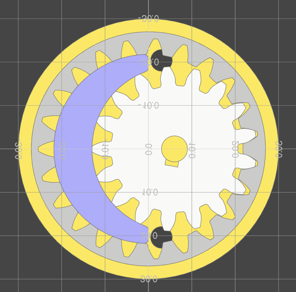
Crescent Gear Pump
This example demonstrates building a gear pump. The design is missing fasteners and seals, but showcases the gear generator and its helper functions for build-123d workflow.
Highlights:
You can use center_location_bottom and center_location_top to align parts with gear centers.
The
radii_data_topmethod generates reference curves for the gear.The
LineOfActionclass is available for generating the line of action between gears.Sometimes converter functions are needed such as
arc_to_b123d()andline_to_b123d(). These convert between py_gearworks’ own geometry classes and build123d geometry.Animation is used from ocp_vscode to visualize the gear meshing. Animation can be non-intuitive, but explaining it is beyond this example.
import py_gearworks as pgw
from build123d import *
from ocp_vscode import *
import numpy as np

set_port(3939)

gearheight = 10
axis_diameter = 6
port_diameter = 5
gearmodule = 2
wall_thickness = 3
clearence = 0.1

gear1 = pgw.SpurGear(
    number_of_teeth=17,
    module=gearmodule,
    height=gearheight,
    addendum_coefficient=1.2,
    profile_shift=0.2,
    z_anchor=0.5,
)
gear2 = pgw.SpurRingGear(
    number_of_teeth=23,
    module=gearmodule,
    height=gearheight,
    addendum_coefficient=1.4,
    dedendum_coefficient=0.8,
    outside_ring_coefficient=2.2,
    profile_shift=0.2,
    z_anchor=0.5,
    # I used the angle kwarg to iteratively check for interference
    angle=0.135,
)


with BuildPart() as gearpart1:
    gear1.build_part()
    with Locations((gear1.center_location_bottom)):
        # notch
        # a rectangular hole on the radius in Y direction
        with Locations((0, axis_diameter / 2, 0)):
            Box(
                length=3,
                width=2,
                height=gearheight,
                mode=Mode.SUBTRACT,
                # location is on the bottom of gear, need to align Z to with MIN
                align=(Align.CENTER, Align.CENTER, Align.MIN),
            )
        # axle hole
        Hole(radius=axis_diameter / 2)

# backlash is specified as a coefficient of module
# clearence is in absolute units, so convert to coefficient of module
gear1.mesh_to(gear2, backlash=clearence / gearmodule, angle_bias=1.0)

gearpart1.part.label = "gear1"
gearpart1.part.location = gear1.center_location_middle


# ring gear needs no modifications
with BuildPart() as gearpart2:
    gear2.build_part()

gearpart2.part.label = "gear2"
# set up rendering colors
gearpart1.part.color = (0.75, 0.75, 0.75)
gearpart2.part.color = (0.6, 0.6, 0.6)


with BuildPart() as housing_base:
    r_outer_gear2 = gear2.max_outside_radius + clearence
    r_outer_wall = r_outer_gear2 + wall_thickness
    # External housing with even-ish wall thickness
    Cylinder(
        radius=r_outer_wall,
        height=gearheight + wall_thickness * 2,
        mode=Mode.ADD,
    )
    Cylinder(radius=r_outer_gear2, height=gearheight, mode=Mode.SUBTRACT)

# split housing base to top and bottom parts
with BuildPart() as housing_bottom:
    add(housing_base.part.split(tool=Plane.XY, keep=Keep.BOTTOM))
    # axle hole
    with Locations((gear1.center_location_bottom)):
        Hole(radius=axis_diameter / 2)
housing_bottom.part.label = "housing_bottom"

with BuildPart() as crescent:
    with BuildSketch():
        # crescent constructed from ring gear inner (dedendum) circle and
        # gear1 outer (addendum) circle.
        with Locations((gear2.center_location_bottom)):
            Circle(radius=gear2.dedendum_radius - clearence, mode=Mode.ADD)
        with Locations((gear1.center_location_bottom)):
            Circle(radius=gear1.addendum_radius + clearence, mode=Mode.SUBTRACT)
        # cut off the right side sharp tips of crescent
        Rectangle(
            width=gear2.addendum_radius,
            height=2 * gear2.addendum_radius,
            mode=Mode.SUBTRACT,
            align=(Align.MIN, Align.CENTER),
        )
        # fillet for good measure
        fillet(vertices(), radius=1)
    extrude(amount=gearheight / 2, both=True)

crescent.part.label = "crescent"
crescent.part.color = (0.5, 0.5, 0.8)


# indicator sketches
addendum_circle_1 = pgw.arc_to_b123d(gear1.radii_data_top.r_a_curve)
addendum_circle_2 = pgw.arc_to_b123d(gear2.radii_data_top.r_a_curve)

# dedendum sketches
dedendum_circle_1 = pgw.arc_to_b123d(gear1.radii_data_top.r_d_curve)
dedendum_circle_2 = pgw.arc_to_b123d(gear2.radii_data_top.r_d_curve)

# involute base circle is not in the radii data
# because radii data was meant to be generic and apply to other gears
base_circle_1 = pgw.arc_to_b123d(gear1.circle_involute_base(z_ratio=1))
base_circle_2 = pgw.arc_to_b123d(gear2.circle_involute_base(z_ratio=1))

loa1, loa2 = pgw.LineOfAction(gear2, gear1, z_ratio=1).LOA_gen()
line_of_action_1 = pgw.line_to_b123d(loa1)
line_of_action_2 = pgw.line_to_b123d(loa2)

# coloring
line_of_action_1.color = (1, 0.2, 0.2)
line_of_action_2.color = (1, 0.2, 0.2)
base_circle_1.color = (0, 0, 0)
addendum_circle_1.color = (0, 0, 0)

# construction of the housing top with channel volumes for oil-flow
channel_thickness = 3
# blocker width is aligned with the distance between the ends of the 2 lines of action
# this is not official pump design advice
blocker_width = min(
    (line_of_action_1 @ 1 - line_of_action_2 @ 1).length,
    (line_of_action_1 @ 0 - line_of_action_2 @ 0).length,
)

with BuildPart() as housing_top:
    add(housing_base.part.split(tool=Plane.XY, keep=Keep.TOP))

    # main cavity + horizontal blocker
    # the top_position rotates with the gear, but we only need the position here
    with Locations(Location(gear2.center_location_top.position)):
        Cylinder(
            radius=r_outer_wall,
            height=channel_thickness + wall_thickness,
            mode=Mode.ADD,
            align=(Align.CENTER, Align.CENTER, Align.MIN),
        )
        Cylinder(
            radius=gear2.addendum_radius,
            height=channel_thickness,
            mode=Mode.SUBTRACT,
            align=(Align.CENTER, Align.CENTER, Align.MIN),
        )
        # horizontal blocker
        Box(
            length=gear2.addendum_radius * 2,
            width=blocker_width,
            height=channel_thickness,
            mode=Mode.ADD,
            align=(Align.CENTER, Align.CENTER, Align.MIN),
        )
    # axle support
    # top location is aligned with gear rotation, but only using position here
    with Locations(Location(gear1.center_location_top.position)):
        r = axis_diameter / 2 + wall_thickness
        Cylinder(
            radius=r,
            height=channel_thickness,
            mode=Mode.ADD,
            align=(Align.CENTER, Align.CENTER, Align.MIN),
        )
        Box(
            length=2 * r,
            width=2 * r,
            height=channel_thickness,
            mode=Mode.ADD,
            align=(Align.MAX, Align.CENTER, Align.MIN),
        )
    with BuildSketch(Location(gear2.center_location_top.position)):
        Circle(radius=gear2.addendum_radius, mode=Mode.ADD)
        Rectangle(
            width=gear2.addendum_radius,
            height=gear2.addendum_radius * 2,
            align=(Align.MAX, Align.CENTER),
            mode=Mode.INTERSECT,
        )
    extrude(amount=channel_thickness)
    r_hole = (gear1.addendum_radius + gear2.dedendum_radius) / 2
    ax_offs = (gear1.center - gear2.center)[0]
    with Locations([(ax_offs / 2, r_hole, 0), (ax_offs / 2, -r_hole, 0)]):
        Hole(radius=port_diameter / 2)

    with Locations(Location(gear1.center_location_top)):
        # axle pocket, should not go all the way through
        Cylinder(
            radius=axis_diameter / 2,
            height=channel_thickness,
            mode=Mode.SUBTRACT,
            align=(Align.CENTER, Align.CENTER, Align.MIN),
        )
housing_top.part.label = "housing_top"
anim_collector = Compound(
    children=(
        [
            gearpart1.part,
            gearpart2.part,
            housing_bottom.part,
            crescent.part,
            housing_top.part,
            line_of_action_1,
            line_of_action_2,
            addendum_circle_1,
            dedendum_circle_2,
        ]
    ),
    label="assembly",
)

duration = 2
n = duration * 30
time_track = np.linspace(0, duration, n + 1)
gear1_track = np.linspace(0, gear1.pitch_angle * 180 / np.pi, n + 1) * duration
gear2_track = np.linspace(0, gear2.pitch_angle * 180 / np.pi, n + 1) * duration
animation1 = Animation(anim_collector)
animation1.add_track("/assembly/gear1", "rz", time_track, gear1_track)
animation1.add_track("/assembly/gear2", "rz", time_track, gear2_track)
show(anim_collector)
animation1.animate(speed=1)
Here you can find the sketches that helped the construction of the crescent and the fluid channels.
